
Introduction
Many solar and backup power systems have more than one charging source.
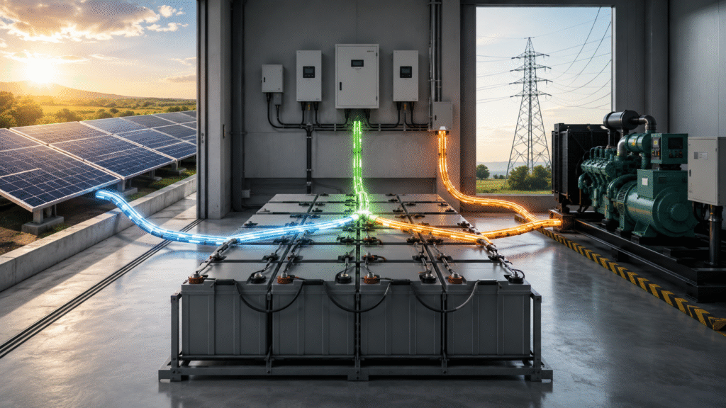
A lead-acid battery bank may receive energy from:
- Solar MPPT controllers
- An inverter/charger connected to the grid
- A diesel or petrol generator
- A standalone AC battery charger
- A wind-charge controller
- A vehicle alternator
- A DC-DC charger
This raises a common system-design question:
Can two or more chargers operate on the same lead-acid battery bank at the same time?
In principle, yes. Multiple correctly configured chargers can charge the same battery bank.
However, they must be coordinated so that:
- The total charging current remains within the battery limit.
- All chargers use compatible voltage settings.
- Cable and protection devices can carry the combined current.
- Temperature compensation is handled correctly.
- Chargers do not enter charging stages at inappropriate times.
- The battery is not overcharged.
The answer is therefore not simply “yes” or “no.” It depends on the battery, chargers, settings, wiring, and control strategy.
How Multiple Chargers Behave on One Battery Bank
Each charger monitors battery voltage and controls its own output.
When the battery is deeply discharged, several chargers may operate at high current simultaneously.
As battery voltage rises:
- One charger may reach its absorption setting first.
- Another charger may reduce current.
- One charger may enter float while another remains in absorption.
- Available solar power may change during the process.
- Generator or grid charging may be switched off.
The battery receives the sum of the currents produced by all active chargers.
For example:
- Solar controller: 40A
- Inverter/charger: 60A
- Standalone generator charger: 30A
The potential combined charging current is:
40A + 60A + 30A = 130A
The battery bank, cables, busbars, breakers, and fuses must be designed for the combined current—not only the rating of the largest charger.
When Multiple Chargers Are Acceptable
Multiple chargers can generally operate together when:
- They charge the same battery-bank voltage.
- They are configured for the same battery chemistry.
- Charging voltages are compatible.
- The total current is acceptable for the battery bank.
- Each charger has appropriate overcurrent protection.
- The DC busbars and cables are correctly sized.
- Temperature compensation does not create conflicting voltage commands.
- Equalization and reconditioning modes are controlled.
- The equipment manufacturers permit parallel operation.
Victron’s official charger documentation includes wiring arrangements for multiple chargers connected in parallel to one battery bank and states that the parallel chargers should use the same charge settings.
The Most Important Limit: Total Charging Current
Each battery manufacturer specifies an acceptable charging-current range.
The correct value depends on:
- Battery type
- Battery capacity
- Plate design
- Temperature
- Cycle application
- Standby application
- Charger voltage
- Required charging time
A current that is suitable for a large OPzS or OPzV bank may be excessive for a smaller AGM or GEL bank.
Trojan’s maintenance guidance, for example, gives a charger-selection range for certain flooded deep-cycle batteries based on the total bank Ah capacity. This recommendation applies to the relevant Trojan battery products and should not be assumed for every lead-acid design.
Example
Assume a 48V 400Ah battery bank has a manufacturer-approved maximum charging current of 80A.
The system includes:
- MPPT solar controller: 50A
- Inverter/charger: 60A
If both operate at full output:
50A + 60A = 110A
This exceeds the stated 80A limit.
Possible solutions include:
- Reducing the inverter/charger current limit
- Reducing the MPPT output limit
- Using system-level current control
- Operating the generator charger only when solar output is low
- Increasing battery capacity, subject to full system redesign
What Happens If Charging Current Is Too High?
Excessive charging current can cause:
- Rapid voltage rise
- Excessive gassing
- High battery temperature
- Water loss in flooded batteries
- Venting in VRLA batteries
- Grid corrosion
- Reduced service life
- Thermal runaway risk
- Charger instability
The battery voltage may rise so quickly that the chargers enter absorption early, even though the battery has not received a complete charge.
High charging current is especially risky when:
- The battery is hot.
- The battery is old.
- The battery is sulfated.
- One battery in the series string is weak.
- The battery bank is smaller than originally planned.
- Temperature compensation is not functioning.
Charging Voltage Settings Must Be Compatible
All active chargers should be configured using values approved for the same battery model.
Review:
- Absorption or boost voltage
- Float voltage
- Equalization voltage
- Absorption duration
- Tail-current logic
- Temperature compensation
- Restart voltage
If one charger is set to 56.4V and another to 58.8V for the same 48V bank, they will not behave as a coordinated system.
The higher-voltage charger may continue pushing current after the lower-voltage charger has entered float.
This does not necessarily mean that current will double throughout the entire charge, but it can create inconsistent charging behavior and excessive battery voltage.
Can an MPPT and Inverter/Charger Work Together?
Yes, this is a common configuration.
The MPPT uses solar power, while the inverter/charger may use grid or generator power.
During bulk charging, both may contribute current.
As the battery reaches the charging-voltage limit:
- The current naturally begins to reduce.
- One charger may enter absorption first.
- The other charger may adjust based on the DC-bus voltage.
- A coordinated system may synchronize charging stages.
Some charger ecosystems allow networked chargers to synchronize their bulk, absorption, and float transitions. Victron documents synchronized operation for compatible solar chargers, allowing several units to charge as one coordinated charger.
Independent chargers may still operate together, but their behavior should be tested.
Will One Charger Damage the Other?
Normally, correctly designed battery chargers tolerate the presence of battery voltage and other charging sources at their output.
However, this should not be assumed for every charger.
Check whether the manufacturer permits:
- Parallel charging
- Reverse voltage at the output
- Connection to an energized DC bus
- Operation with other charger brands
- Generator-powered operation
Do not connect chargers in series unless the equipment was specifically designed for that arrangement.
Why One Charger May Show Zero Current
When several chargers are connected, one may show very little or no output.
This can happen because:
- Another charger has raised the battery voltage.
- The battery has reached absorption or float voltage.
- The solar controller has limited available PV power.
- The charger’s voltage setting is slightly lower.
- The charger is in standby.
- The system loads are consuming the available current.
This does not necessarily indicate a fault.
For example, when the AC charger holds the battery at a higher voltage, the MPPT may interpret the battery as nearly full and reduce its output.
Can Solar Be Prioritized Over the Grid or Generator?
Yes, depending on the charger and inverter-control functions.
Common strategies include:
Current Limiting
Reduce the AC charger’s current so solar provides most of the energy during daylight.
Voltage Offset
Configure the grid charger with a slightly lower target or standby strategy, provided the values remain within the battery manufacturer’s limits.
Scheduled Generator Charging
Run the generator only:
- At night
- After several low-solar days
- Below a defined battery voltage
- At a low SOC threshold
- During high-load periods
External Energy Management
A controller can start, stop, or limit chargers according to:
- Solar output
- Battery voltage
- Battery current
- Time of day
- Generator status
- Load demand
Do not create large charging-voltage differences merely to prioritize one energy source. Charging priorities should be managed without violating the battery specification.
Generator Charging Requires Special Attention
A generator may power:
- The inverter/charger
- A separate AC battery charger
- AC loads at the same time
The generator must be sized for:
- Charger input power
- Charger power factor
- Load power
- Startup surge
- Altitude and temperature derating
- Required operating margin
An undersized generator may experience:
- Unstable voltage
- Frequency variation
- Overload
- Charger derating
- Repeated shutdown
- Poor absorption charging
A very large charger does not automatically reduce generator runtime if the battery cannot safely accept the available current.
Each Charger Needs Protection
Every charging branch should normally have appropriate DC protection.
The design may include:
- A fuse or breaker for each charger
- A main battery-bank fuse
- Positive and negative busbars
- DC disconnect devices
- Cable protection
- Proper grounding or bonding
- Clear circuit labeling
The protection rating must match:
- Charger maximum current
- Cable ampacity
- DC system voltage
- Prospective short-circuit current
- Equipment manufacturer instructions
Protection devices should be installed as close as practical to the battery or DC busbar according to the system design.
The official parallel-charger diagram from Victron shows individual charger protection and a main battery protection device.
Combined Current Must Be Considered in Cable Sizing
Suppose two chargers each produce 50A.
The individual branch cables may each carry 50A, but the cable between the common busbar and battery may carry up to 100A.
Therefore:
- Charger branch cables are sized for individual output.
- Common busbar cables are sized for combined output.
- The main fuse is coordinated with the common cable.
- Busbars are rated for the total current.
The same principle applies when the battery is simultaneously charging and powering loads.
Charging While Loads Are Running
A battery bank can normally be charged while the inverter or DC loads are operating.
However, charger displays can become confusing.
For example:
- Charger output: 80A
- DC load consumption: 50A
- Net battery charging current: 30A
The charger may show 80A, but only 30A is actually entering the battery.
A battery shunt installed at the main battery negative connection provides a clearer measurement of net battery current.
Large operating loads can also prevent the charger current from falling below the tail-current threshold. A battery monitor may therefore fail to recognize a fully charged condition.
Temperature Compensation Problems
Lead-acid charging voltage should normally be adjusted according to battery temperature.
Problems can occur when:
- One charger has a temperature sensor and another does not.
- Sensors are installed on different batteries.
- One sensor measures room temperature instead of battery temperature.
- Chargers use different compensation coefficients.
- One charger compensates voltage while another remains fixed.
Ideally, coordinated chargers should use the same battery-temperature information.
If this is not possible, confirm that the resulting voltage range remains within the battery specification.
Equalization and Reconditioning Modes
Automatic equalization or reconditioning should be treated carefully when multiple chargers are present.
Potential problems include:
- One charger entering equalization while others remain in float
- Combined current becoming excessive
- Charging voltage exceeding the limits of connected equipment
- VRLA batteries receiving an unsuitable high-voltage charge
- Loads remaining connected during equalization
Equalization should only be enabled when approved for the selected battery and complete system.
Do not enable equalization on every charger simultaneously unless the battery and charger manufacturers specifically permit it.
Can Chargers from Different Brands Be Used?
Technically, chargers from different brands may operate on the same battery bank if their outputs and charging profiles are compatible.
However, mixed-brand systems have additional risks:
- No synchronized charging stages
- Different voltage measurement accuracy
- Different temperature compensation
- Different absorption timing
- Different restart logic
- No shared current limit
- Difficult troubleshooting
For critical projects, chargers with a common control or communication platform are easier to manage.
What If the Chargers Use Different Battery Types?
All chargers connected to one battery bank must be configured for that battery bank.
Do not connect:
- One charger set for lithium
- One charger set for AGM
- One charger set for flooded batteries
to the same lead-acid bank.
Even when the nominal voltage is the same, charging profiles can differ significantly.
Practical Configuration Example
Assume the system has:
- Battery bank: 48V 600Ah GEL
- Solar MPPT maximum output: 60A
- Inverter/charger maximum output: 80A
- Manufacturer-approved total charging current: 90A
The theoretical combined current is:
60A + 80A = 140A
A possible configuration is:
- MPPT limit: 60A
- Inverter/charger limit: 30A when solar is available
- Maximum combined current: 90A
At night or during poor weather, the inverter/charger could be increased, provided the total battery-current limit is still respected.
The exact settings must be based on the selected battery data sheet and system-control capability.
Commissioning Checklist
Before operating multiple chargers:
- Confirm the battery model and capacity.
- Obtain the recommended charging parameters.
- Calculate the maximum combined charging current.
- Configure every charger for the same battery type.
- Check absorption and float voltages.
- Review temperature compensation.
- Disable unapproved equalization modes.
- Size branch and common cables.
- Install individual protection devices.
- Confirm busbar ratings.
- Start one charger at a time.
- Measure battery current with a shunt or clamp meter.
- Activate all chargers.
- Monitor total current and battery temperature.
- Compare individual battery voltages.
- Confirm correct absorption and float transitions.
- Test the system with normal loads operating.
Common Mistakes
Adding Charger Ratings Without Checking Battery Capacity
The battery may not safely accept the combined current.
Using Different Charging Voltages
One charger may continue charging after another has entered float.
Sizing the Main Cable for One Charger Only
The common cable must support combined current.
Leaving Automatic Equalization Enabled
This can expose the battery and connected equipment to inappropriate voltage.
Ignoring Loads During Charging
Charger current and battery current are not always the same.
Assuming All Chargers Communicate
Independent chargers normally respond only to the voltage they measure unless a communication network is provided.
Using One Temperature Sensor for the Wrong Location
The sensor should represent the actual battery temperature.
Frequently Asked Questions
Can an MPPT and inverter charger charge the battery simultaneously?
Yes, provided their settings are compatible and the total charging current remains within the battery limit.
Will two 50A chargers always produce 100A?
Not necessarily. Their output depends on battery voltage, charging stage, available input power, settings, and connected loads.
Can solar and generator charging damage the battery?
They can if the combined current or charging voltage exceeds the battery specification.
Can I use chargers from different manufacturers?
Possibly, but their voltage, current, temperature compensation, and charging-stage behavior must be verified.
Which charger controls the battery voltage?
Each charger regulates its own output. The actual battery voltage results from the combined operation of the chargers, battery, and loads.
Do multiple chargers need separate fuses?
Each charging branch and the main battery connection should have coordinated protection according to the system design and equipment instructions.
Can I charge the battery while the inverter supplies loads?
Yes. The net charging current equals total charger current minus the DC current used by the inverter and other loads.
Conclusion
Solar, grid, generator, and standalone chargers can charge the same lead-acid battery bank, but they must be treated as one combined charging system.
The design must control:
- Total charging current
- Charging voltage
- Absorption duration
- Float voltage
- Temperature compensation
- Cable capacity
- Busbar capacity
- Fuse and breaker ratings
- Equalization functions
- Charger coordination
For a project-specific charging configuration, provide the battery model, bank voltage and Ah capacity, battery technology, MPPT model, inverter/charger model, generator-charger rating, maximum load, cable sizes, and recommended battery charging parameters.