
Introduction
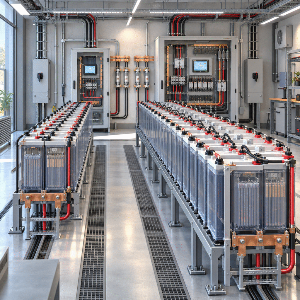
One of the most common industrial applications for 2V OPzV batteries is the high-reliability DC power system used in:
- Electrical substations
- Power plants
- Utility control systems
- Switchgear stations
- Railway systems
- Oil and gas facilities
- Industrial emergency systems
These systems are often described as:
110V DC
or
220V DC
battery systems.
A common mistake is to treat these values as if the design were as simple as:
110V ÷ 2V = 55 cells
or
220V ÷ 2V = 110 cells
That calculation provides a useful nominal starting point—but it is not enough to finalize the battery design.
The correct cell count must satisfy the complete DC voltage window:
- Maximum allowable float voltage
- Maximum boost voltage
- Minimum equipment operating voltage
- End-of-discharge voltage
- Cable voltage drop
Modern substation-battery design guidance likewise emphasizes that cell count should be derived from the actual DC bus operating window rather than chosen only from nominal voltage.
Understanding Nominal Voltage
A lead-acid cell is commonly described as a:
2V cell
but its actual operating voltage changes with:
- State of charge
- Charging stage
- Load
- Temperature
For example, an OPzV cell on float may operate above 2V, while near the end of discharge it may fall significantly below 2V.
Therefore:
Nominal voltage is not charger voltage.
and
Nominal voltage is not minimum operating voltage.
This distinction is critical in high-voltage DC systems.
Common Starting Point for Cell Count
A nominal 110V system may use approximately:
55 × 2V cells = 110V nominal
A nominal 220V system may use approximately:
110 × 2V cells = 220V nominal
However, some projects use different cell counts because of equipment voltage limits and specified end-of-discharge conditions.
The final number must be calculated.
Check 1: Maximum Float Voltage
Suppose the selected OPzV manufacturer’s float recommendation is:
Uf volts per cell
and the system contains:
N cells
Then:
Total Float Voltage = N × Uf
Example only:
If a project uses 55 cells and the approved float setting is approximately 2.25V/cell:
55 × 2.25 = 123.75V
The protected DC equipment must tolerate this voltage continuously.
Do not use the example 2.25V/cell without checking the selected OPzV model.
Check 2: Maximum Boost or Equalizing Voltage
The battery bank may occasionally operate above normal float voltage during:
- Boost charge
- Recovery charge
- Equalizing charge, where manufacturer-approved
Therefore:
Maximum battery charging voltage
may be substantially higher than nominal DC bus voltage.
Before selecting the final cell count, verify that:
- Protection relays
- Switchgear coils
- PLCs
- Communication equipment
- DC lighting
- Monitoring equipment
can tolerate the maximum charger output.
A system may be safe at float but exceed equipment limits during boost charging if the cell count is selected incorrectly.
Check 3: Minimum End-of-Discharge Voltage
At the end of an outage, cell voltage falls.
If the battery manufacturer specifies a particular final voltage at the project discharge rate:
Total End Voltage = Number of Cells × Final Voltage per Cell
The resulting voltage must remain high enough for critical loads.
For example, if the selected battery’s applicable discharge table uses 1.80V/cell:
For 55 cells:
55 × 1.80 = 99V
The critical DC equipment must still operate correctly at this voltage after cable losses are considered.
This is why cell count cannot be selected using nominal voltage alone.
The Real Design Window
A good engineering process checks both extremes:
Upper Limit
Can the DC system tolerate maximum charging voltage?
Lower Limit
Can the DC system still operate at battery end voltage?
The battery configuration must fit inside both constraints.
Capacity Sizing Comes After Voltage Sizing
Cell count determines system voltage.
Ah capacity determines backup duration.
These are separate design steps.
Suppose the critical DC load is:
20A
and required autonomy is:
5 hours
The simple energy requirement would be:
20A × 5h = 100Ah
But a real stationary-battery calculation should also consider:
- Aging margin
- Temperature
- Discharge rate
- Design margin
- Future load growth
- Manufacturer discharge data
Therefore, selecting a 100Ah battery simply because the mathematical load is 100Ah may be inadequate.
Use Manufacturer Discharge Tables
OPzV capacity should be selected using the required duty.
For example, different projects may require:
- 1-hour high-rate discharge
- 3-hour backup
- 5-hour backup
- 8-hour backup
- 10-hour backup
A 1000Ah C10 battery does not deliver identical usable Ah at every discharge rate.
Use the manufacturer’s:
- Constant-current table
- Constant-power table
rather than only the nominal Ah label.
Substation Loads Are Not Always Constant
A substation DC system may include:
Continuous Loads
- Protection relays
- Communication equipment
- SCADA
- Indicators
- Control electronics
Short-Duration Loads
- Breaker trip coils
- Breaker closing coils
- Motor drives
- Emergency operations
The battery must support both:
energy requirement
and
maximum short-duration current.
A battery with enough Ah may still be unsuitable if it cannot support the required peak current without excessive voltage sag.
Charger Capacity Must Be Sized Separately
The charger normally needs to support:
- Continuous DC loads
- Battery recharge current
For example:
- Continuous load: 15A
- Desired battery recharge current: 40A
A preliminary charger requirement may therefore be at least:
55A plus design margin
subject to charger redundancy and project specifications.
If the charger is sized only for the battery and ignores continuous load, recharge can take much longer than expected.
Redundant Chargers
Critical substation systems frequently use redundant charger arrangements.
Possible configurations include:
- One duty + one standby
- Two chargers sharing load
- Redundant AC supply
The design should consider what happens if:
- One charger fails
- One AC source fails
- A charger is removed for maintenance
Battery capacity should not be used to compensate for an obviously inadequate charger redundancy strategy.
Temperature Compensation
OPzV float voltage normally requires temperature consideration.
Battery rooms in:
- Middle East
- Africa
- Southeast Asia
may operate significantly above the standard reference temperature unless air-conditioned.
A charger applying an uncompensated room-temperature float voltage to a hot battery bank can increase:
- Charging current
- Grid corrosion
- Venting risk
- Battery aging
Use the manufacturer’s specified temperature-compensation coefficient.
Battery Room Temperature Also Affects Capacity
Cold temperature reduces available capacity.
High temperature accelerates aging.
Therefore, system designers should distinguish:
capacity requirement from service-life requirement.
A battery may initially provide sufficient Ah in a hot room while still aging much faster than expected.
Individual Cell Monitoring Is Essential
A 220V system containing roughly a hundred 2V cells can hide one weak unit very easily.
Suppose:
- 109 cells remain healthy.
- 1 cell loses capacity.
The total float voltage may still look normal.
During a long utility outage, however, that one cell may reach its end voltage first.
Therefore, critical OPzV systems should trend:
- Individual cell voltage
- Cell temperature
- Internal resistance or impedance
- Total string voltage
- Float current
IEEE 1188-2025 is the active recommended practice for maintenance, testing, and replacement of stationary VRLA batteries.
Do Not Monitor Only Total Voltage
A charger displaying:
248V
does not prove that all cells are healthy.
The total might contain:
- One low-voltage cell
- Several slightly high-voltage cells
that still add up to the expected total.
Individual monitoring provides much more diagnostic value.
Establish Baseline Values at Commissioning
When the battery bank is new, record:
- Cell voltage
- Internal resistance
- Cell temperature
- Connection resistance
These measurements become the reference for future maintenance.
Without baseline values, a technician may know that a cell measures:
0.75mΩ
but not know whether:
- It started at 0.45mΩ
- It started at 0.72mΩ
Those situations mean very different things.
Capacity Testing
Routine voltage measurement cannot prove battery capacity.
A controlled capacity test provides direct evidence of whether the bank can support the required duty.
For VRLA stationary applications, IEEE 1188 provides the framework for maintenance and testing practices.
For a utility tender, the acceptance and performance-test requirements should be defined before battery purchase.
Designing for End of Life
An industrial battery bank should not be sized only to meet the load when brand new.
The project should consider:
- Aging margin
- Required end-of-life capacity
- Temperature correction
- Future load expansion
This is particularly important for substations designed for long service periods.
Example Design Logic for a 110V System
Assume a project requires:
- Nominal DC system: 110V
- Critical equipment has defined maximum and minimum voltage limits
- 5-hour backup
- OPzV battery selected
Engineering sequence:
Step 1
Determine permitted maximum bus voltage.
Step 2
Determine minimum equipment operating voltage.
Step 3
Obtain OPzV manufacturer:
- Float voltage
- Boost voltage
- End voltage
Step 4
Select a preliminary cell count.
Step 5
Verify maximum charger voltage:
Cell Count × Maximum Approved Charge Voltage
Step 6
Verify minimum battery voltage:
Cell Count × Applicable Final Voltage
Step 7
Calculate Ah requirement using discharge tables.
Step 8
Apply:
- Aging factor
- Temperature factor
- Design margin
Step 9
Size charger.
Step 10
Confirm monitoring and protection.
This is more reliable than simply saying:
“110V means 55 cells.”
220V Systems Require Even More Attention to Weak Cells
With approximately twice as many cells as a 110V system, there are more individual units to:
- Inspect
- Record
- Maintain
- Compare
A battery monitoring system becomes particularly valuable.
One deteriorating cell can remain hidden in a long string until a discharge event occurs.
Protection and Isolation
Large OPzV battery banks can deliver very high short-circuit current.
Project design should include:
- Battery isolation
- DC protection
- Proper cable sizing
- Correct breaking capacity
- Safe maintenance access
Do not select fuses or breakers based solely on normal continuous load.
Short-circuit capability and DC interruption requirements must also be considered.
Cable Voltage Drop
A 110V or 220V battery system generally has lower current than an equivalent low-voltage battery system for the same power.
However, long cable runs in substations can still produce meaningful voltage drop.
At end of discharge, every volt may matter.
Verify the voltage available at:
the actual critical load
not only at battery terminals.
One Battery Bank or Two?
Some critical facilities use dual battery systems.
Advantages can include:
- Maintenance flexibility
- Redundancy
- Reduced single-point failure
But this increases:
- Equipment cost
- Charger requirements
- Monitoring complexity
- Space
The correct architecture depends on project criticality and applicable specifications.
Information to Request Before Quoting an OPzV Substation Project
A professional battery supplier should ask for more than:
“Need 110V 300Ah OPzV.”
Request:
- Nominal DC voltage
- Maximum allowable bus voltage
- Minimum allowable bus voltage
- Continuous load
- Peak load
- Required backup duration
- Ambient temperature
- Charger configuration
- Existing cell count, if replacing a bank
- Required standard
- Required design life
- Available battery-room dimensions
Without this information, the quote is only preliminary.
Common Tender Mistakes
Specifying Only Ah
The discharge rate and end voltage may be missing.
Specifying 110V but Not Voltage Window
Final cell count cannot be verified properly.
Ignoring Battery-Room Temperature
Capacity and life can both be affected.
Selecting Charger Current Without Continuous Load
Recharge time becomes too long.
No Individual Cell Monitoring
Weak cells remain hidden.
Replacing an Old Bank with Different Cell Count Without Checking Equipment Limits
The new charger voltage may no longer match the existing DC equipment.
Frequently Asked Questions
How many 2V OPzV cells are required for a 110V system?
Around 55 cells is a common nominal starting point, but final cell count must be checked against maximum charging voltage and minimum end-of-discharge voltage.
How many cells are used in a 220V DC battery bank?
Around 110 × 2V cells is a common nominal configuration, but the project voltage window determines the final design.
Can OPzV batteries be used in substations?
Yes. OPzV batteries are widely suited to stationary applications requiring long-life DC backup with low routine maintenance.
Is total string voltage enough for maintenance?
No. Individual cell voltage, temperature, resistance, and periodic capacity testing provide much better information.
Should charger voltage simply be 110V or 220V?
No. A battery charger normally operates above nominal battery voltage during float and boost charging.
Can the same OPzV size be used for every 110V substation?
No. Ah capacity depends on load, autonomy, temperature, discharge rate, and design margin.
Conclusion
Designing a reliable 110V or 220V OPzV DC battery system requires more than dividing the nominal voltage by 2V.
The design should coordinate:
- Cell count
- Float voltage
- Maximum charging voltage
- End-of-discharge voltage
- Ah capacity
- Load profile
- Charger current
- Battery temperature
- Weak-cell monitoring
- Capacity testing
For substation, utility, telecom, railway, and industrial DC projects, provide the full DC load profile and voltage window before final battery selection.
This allows the battery supplier to recommend:
the correct number of cells + correct Ah capacity + correct charging parameters
rather than supplying a generic battery bank based only on nominal voltage.
Suggested Internal Links:
- How to Choose Between OPzV and OPzS Batteries for Energy Storage Systems
- Environmental and Operational Factors Affecting OPzV Battery Performance
- OPzV vs OPzS Battery Life, Cycle Performance, and Cost Analysis