
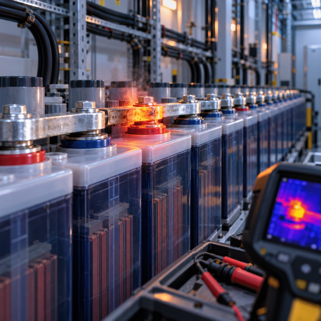
What Is an Intercell Connector?
In a series battery string, the positive terminal of one cell is connected to the negative terminal of the next. The connection may use:
- Copper bar
- Lead-plated copper connector
- Flexible cable
- Flexible copper link
The complete electrical path contains:
battery terminal → contact interface → connector → contact interface → next battery terminal.
Every interface introduces some resistance. A correctly assembled connection keeps this resistance very low. A poor connection can gradually become a significant weak point.
Why a Tiny Resistance Can Create Serious Heating
Electrical heat follows: P = I²R
where:
- P = heat power
- I = current
- R = resistance
Suppose a connection has: 0.5 mΩ of additional resistance.
At: 100A
the heating is: 100² × 0.0005 = 5W
At: 500A
the same poor connection produces: 500² × 0.0005 = 125W
At: 1000A
it becomes: 500W
This illustrates why a connector that appears harmless during light float operation can become extremely hot during a heavy discharge.
Float Voltage Testing Can Miss the Problem
During normal standby operation, charging current may be relatively low. A high-resistance connector may therefore show:
- Little temperature increase
- Very small voltage drop
The battery bank appears normal. Then the utility supply fails. The UPS or inverter suddenly draws hundreds of amps. The poor connection experiences:
- High voltage drop
- Rapid heating
- Further resistance increase
The fault becomes obvious only under load. This is why connection testing is much more useful when meaningful current is flowing.
Symptom 1: One Terminal Becomes Much Hotter Than the Others
Localized terminal heating is one of the clearest signs. For example:
- Most connectors: 28–31°C
- Connector at Cell 37: 63°C
This is very different from an entire battery case being hot.
Entire Battery Hot
Possible internal battery issue.
Connector or Terminal Hot
More likely:
- Loose bolt
- Poor contact
- Corrosion
- Damaged connector
- Incorrect torque
Thermal imaging can help distinguish these conditions.
Symptom 2: Total String Voltage Is Normal Until a Heavy Load Starts
Suppose a 110V OPzV bank appears normal on float. When a large load starts:
- Battery voltage drops sharply.
- DC equipment alarms.
- Inverter shuts down.
After the load stops:
- Voltage immediately recovers.
The batteries may be blamed. But the real issue may be voltage loss in:
- Intercell connectors
- Main battery cables
- Fuse holders
- Breakers
The correct troubleshooting method is to measure the voltage across individual connections while current is flowing.
How Voltage-Drop Testing Works
A healthy connector should have very little voltage difference from one side to the other. Place the meter probes across the connection. For example:
Probe A: terminal post of Cell 12
Probe B: terminal post of Cell 13
with the connector between them. Apply a stable current.
Record:
Voltage Drop = ΔV
Then compare the reading with all other comparable connections.
The most useful information is often:
Which connection has substantially more voltage drop than the rest?
rather than trying to use one universal microvolt threshold.
Why Current Must Be Recorded
Voltage drop alone has limited value.
Suppose:
Test A
Drop = 20mV
Current = 500A
Test B
Drop = 20mV
Current = 50A
These do not represent the same resistance.
Using: R = V ÷ I
Test A: 0.020 ÷ 500 = 0.00004Ω = 0.04mΩ
Test B: 0.020 ÷ 50 = 0.0004Ω = 0.4mΩ
Therefore, record:
- Voltage drop
- Current
together.
Connection Resistance Can Be Calculated
If the test current is reasonably stable: Connection Resistance = Voltage Drop ÷ Current
For example:
Voltage drop: 30mV
Current: 300A
Resistance: 0.030 ÷ 300 = 0.0001Ω
or: 0.1mΩ
This can be recorded as a baseline. Later maintenance measurements can show whether resistance is increasing.
The Best Reference Is Usually the Rest of the Bank
Suppose 54 similar connectors measure: 0.03–0.06mΩ
while one measures: 0.28mΩ
That one connection deserves attention. This comparative approach is useful because:
- Different connector designs have different normal resistance.
- Different test equipment produces different results.
- Cable links differ from rigid copper bars.
Do not use one universal resistance value for every OPzV and OPzS installation.
Reason 1: Incorrect Terminal Torque
One of the most common causes is incorrect tightening.
Too Loose
Creates:
- Small contact area
- Higher resistance
- Heating
- Possible arcing
Too Tight
Can damage:
- Terminal post
- Battery lid
- Thread
- Seal
The correct torque comes from the battery manufacturer.
Do not assume: M10 terminal = same torque on every battery brand.
Terminal design matters.
Reason 2: Oxidized or Contaminated Contact Surfaces
Electrical contact surfaces should be clean. Possible contamination includes:
- Oxidation
- Dust
- Acid residue
- Corrosion
- Dirt
These materials increase contact resistance. For OPzS installations, acid mist and electrolyte contamination can make connection maintenance especially important.
Reason 3: Corrosion from Acid Mist
Flooded OPzS batteries can release gas and acid mist during charging. Over time, this can contribute to corrosion around:
- Terminals
- Copper connectors
- Hardware
- Racks
Corrosion can gradually increase connection resistance. A connector may look acceptable from above while corrosion develops underneath the contact surface. If resistance is abnormal, remove and inspect the connection according to the site’s safe isolation procedure.
Reason 4: Poor Cable-Lug Crimping
Flexible intercell or main cables may use crimped lugs. Problems include:
- Incorrect crimp tool
- Wrong lug size
- Insufficient compression
- Broken conductor strands
- Corrosion inside the barrel
A poor crimp can create heating even when the terminal bolt itself is correctly tightened. Thermal imaging often shows the hottest point around the lug barrel.
Reason 5: Mechanical Stress on the Terminal
Large cables can be heavy and stiff. If the cable pulls sideways on the terminal, it may create:
- Poor contact
- Seal damage
- Terminal stress
Cable routing should not transfer excessive mechanical force into the battery terminal.
Reason 6: Battery Movement
Battery racks can experience:
- Settlement
- Vibration
- Seismic movement
- Installation movement
A previously correct connector may become mechanically stressed or loose. This is one reason periodic connection inspection remains important even after correct commissioning.
Reason 7: Incorrect Connector Size
A connector that is too small for the operating current can become hot even when the contact surfaces are perfect.
Check:
- Cross-sectional area
- Material
- Continuous current
- Short-duration current
Do not simply copy a connector from a much smaller battery bank.
Reason 8: Connector Installed in the Wrong Position
Some large cells use:
- Multiple terminals
- Multiple parallel intercell links
If one required link is omitted, current may concentrate through the remaining connector.
This can create:
- Excess heating
- Unequal current density
Always follow the manufacturer’s connection arrangement.
Reason 9: Improvised Replacement Connector
During emergency maintenance, technicians sometimes replace a missing copper bar with:
- Smaller cable
- Different metal bar
- Temporary jumper
The system may operate, but the resistance can differ significantly from the original design. Temporary repairs should not automatically become permanent installations.
OPzV vs. OPzS Connection Environment
The electrical principles are similar, but the environment can differ.
OPzV
Normally has less acid-mist exposure. Connection problems more commonly relate to:
- Torque
- Mechanical issues
- Aging hardware
OPzS
Additional factors include:
- Acid mist
- Electrolyte contamination
- Watering activity
- Corrosion
OPzS terminals therefore benefit from careful visual inspection.
Do Not Retorque Energized High-Current Connections Casually
A technician may see a hot connector and immediately reach for a wrench. This can be dangerous. Large battery banks can deliver very high fault current. Follow the approved:
- Isolation procedure
- PPE requirements
- Lockout/tagout procedure
before disturbing battery hardware.
Thermal Imaging Is Extremely Useful
A thermal camera can inspect many connectors quickly. During a controlled load, scan:
- Every intercell connection
- Main positive cable
- Main negative cable
- Breakers
- Fuse holders
- Busbars
Look for outliers. For example:
Most connectors: 30°C
one connector: 57°C
This immediately identifies a location for closer electrical testing.
Temperature Alone Is Not Enough
A warm connector may simply carry more current. This is especially relevant in parallel strings. Therefore, combine thermal data with:
- Current
- Voltage drop
- Connection resistance
to avoid false diagnosis.
Main Cable Voltage Drop Should Also Be Tested
Do not inspect only intercell connectors. The complete path includes:
battery bank → fuse/breaker → main cable → busbar → inverter/load
Measure loaded voltage at:
- Battery terminal
- Busbar
- Load input
This can reveal where the voltage is being lost.
Example: 48V OPzV Telecom Bank
The customer reports:
- Battery runtime unexpectedly short
- Low-voltage alarm during transmitter startup
Battery capacity test appears acceptable.
Loaded measurements show:
Battery terminals: 48.2V
but:
DC distribution panel: 45.9V
Further inspection finds a high-resistance main battery connection.
The correct repair is not:
Replace all batteries.
It is: Correct the high-resistance connection.
Example: 110V Substation Battery
During a trip-coil test, one intercell connector becomes much hotter than the others.
Measured:
- Current: high
- Voltage drop across connector: several times neighboring connectors
After safe isolation:
- Terminal surface is found corroded.
- Connector contact area is reduced.
Cleaning/replacement and correct reassembly restore normal behavior. This illustrates the value of connection testing under actual operating current.
Build a Baseline at Commissioning
For critical projects, record:
- Connection resistance
- Terminal torque
- Cell voltage
- Temperature
when the battery is new. Future inspections can then compare: current value vs. commissioning value
rather than guessing.
Connection Resistance vs. Battery Internal Resistance
These are different measurements.
Battery Internal Resistance
Reflects the internal electrochemical/electrical condition of the cell.
Connection Resistance
Reflects the external electrical interface between components. A battery tester may combine both depending on probe placement. Know what your instrument is actually measuring.
Recommended Troubleshooting Sequence
Step 1 — Apply a Stable Load
Use a safe, controlled operating condition.
Step 2 — Measure Total Current
Record the current.
Step 3 — Thermal Scan
Identify hot spots.
Step 4 — Measure Voltage Drop
Test suspect connectors.
Step 5 — Compare All Connections
Look for outliers.
Step 6 — Safely Isolate the Bank
Before mechanical work.
Step 7 — Inspect Contact Surfaces
Look for:
- Corrosion
- Loose hardware
- Mechanical damage
Step 8 — Reassemble to Manufacturer Specification
Use approved hardware and torque.
Step 9 — Repeat the Loaded Test
Confirm improvement.
Common Mistakes
Measuring Only with No Load
High-resistance faults may remain hidden.
Tightening Every Bolt More
Over-tightening can damage terminals.
Replacing a Battery Because Its Terminal Is Hot
The cell may be healthy.
Ignoring Corrosion Under the Connector
External appearance can be misleading.
Comparing Connection Resistance Across Different Connector Designs
Use comparable connections.
Performing Mechanical Work on an Energized Bank
Large stationary batteries require proper isolation.
Frequently Asked Questions
What causes an OPzV or OPzS terminal to become hot?
Common causes include loose hardware, corrosion, poor contact surfaces, undersized connectors, or poor cable-lug crimps.
Can a bad connector reduce battery backup time?
Yes. Excessive voltage drop can cause the inverter or DC load to reach its low-voltage limit earlier.
Can total battery voltage remain normal?
Yes. The problem may only become significant when high current flows.
Should I use terminal temperature or voltage drop?
Use both. Thermal imaging locates possible faults; loaded voltage-drop testing quantifies electrical loss.
Is more torque always better?
No. Use the manufacturer’s specified terminal torque.
Can connection resistance be trended?
Yes. Baseline measurements are useful for detecting deterioration over time.
Conclusion
A large OPzV or OPzS battery bank is only as reliable as its electrical connections.
A high-resistance intercell connector can create:
voltage drop + heat + early shutdown + reliability risk
even when every individual battery is healthy.
For critical systems, include:
loaded voltage-drop testing + thermal inspection + connection-resistance trending
in the maintenance program.
This helps distinguish a true battery failure from a much simpler—but potentially dangerous—connection problem.